AUTOMATION
AUTOMATE YOUR LIFE
Automation can be hard to explain.....
But its basically having electronic devices controlling other devices :)
This is now being refereed to as "The Internet Of Things" or IOT.
The below items are a few examples of projects i have done. Bare in mind, this is all prototype, hand made with no help from 3d printers etc.
All from Concept, Design, Construction, Testing and Trial.
Ignore the mess.... Its something id make pretty if it was for someone...
Lets design something for you.... What do you need done for you?
I'll start with a box I made to control and remotely monitor /control water levels and lighting
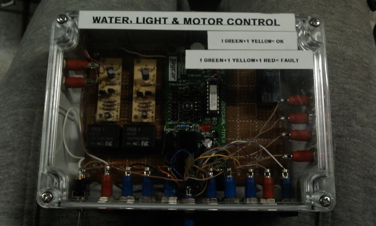
So the above is the Completed box.. .... but as you may notice there are 2 versions of this in the pics.
When I built this... I had no idea I would be looking at building more... and I no longer have it :(
But it served me well.
Now the Idea is to remotely control (via web or sms messages), locally control (via PC or in person) and monitor (so remote alarms like sms or email)
-2 pump outlets (for say 2 overflow fish filters or plant watering pipes). Via a thin twin core cable at the outlet end
-Water or nutrient container low and high levels and auto fill if desired with the use of a solenoid on mains water supply.
-Timing control of all pumps or filters
Ill go through the design from start to finish
Lets start with electrical design drawings. All hand drawn and in a ladder format.
To any Sparky.s reading this.....How good are you at your electrical drawings?
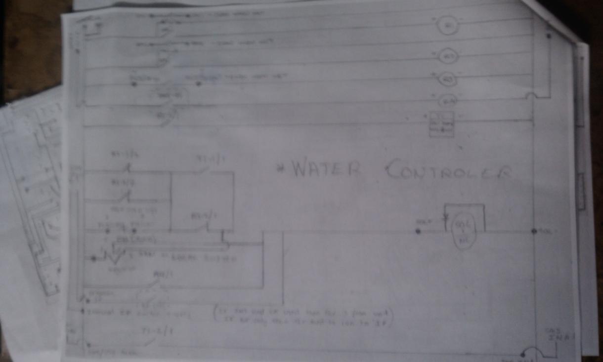
Sorry.... Its actually really blurry but ill eventually draw this out in design spark or something.
From that i basically design a Printed Circuit Board (PCB) Layout.
But this is after a heap of testing and trial of different components. Like these previous versions
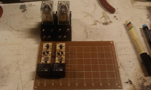
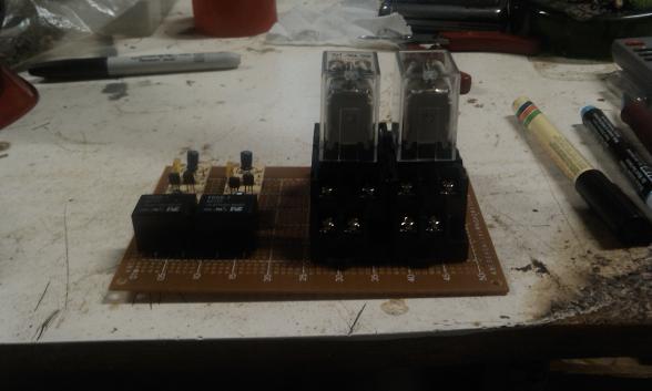
I basically started with big click clacks and worked my way down as testing progressed successfully.
It may look rough... but i never had an issue.... there is no point automating something if you have to constantly be involved in the process :)
Below is breadboards drawn with conductive pen by hand, hard to solder but actually quite reliable for low current applications.. Oh btw..
All 12VDC or less
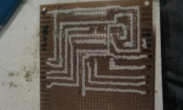
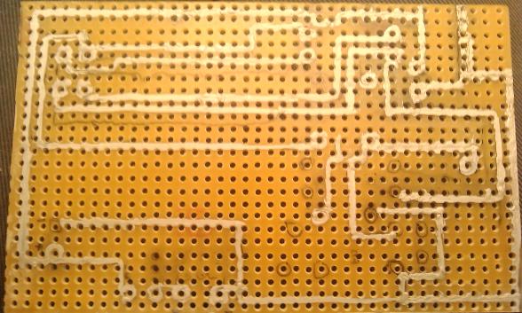
Eventually leading to this drawing for a hand sketched, Hand bathed PCB.
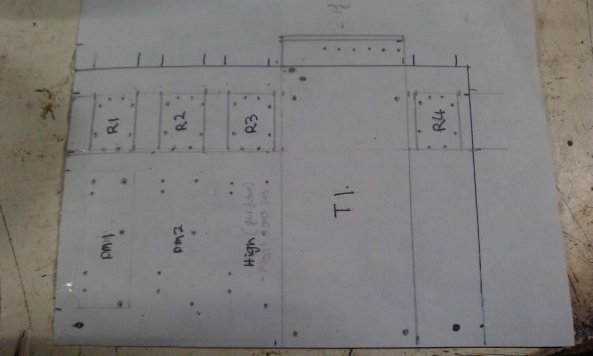
FRONT
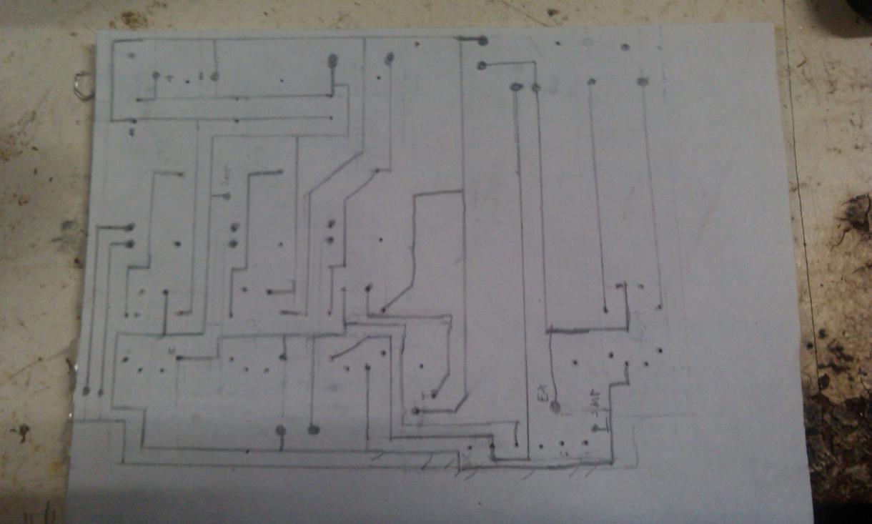
BACK
As mentioned... i had several versions... hard to put in a good order so below is basically the prototype bread boarded and soldered before i got to an etched PCB design
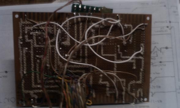
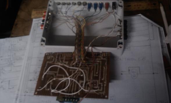
Rough as anything... I know... I know.
I'm OCD (not when it comes to spelling or punctuation though ;))
So its not something Im proud of.... but its part of the process...
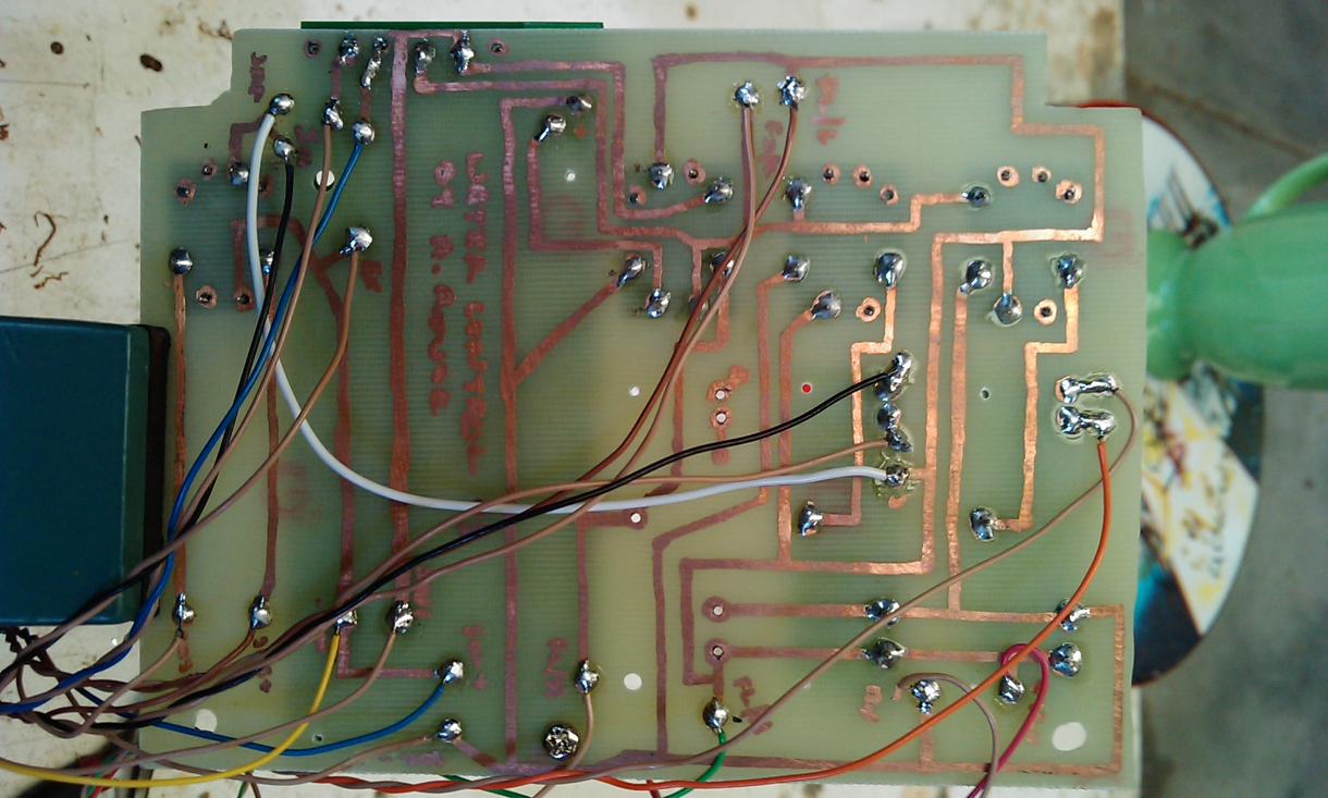
But I turned it into the below... again hand drawn with an acid proof pen on a copper board. All holes drilled with a Dremel bench press and a hand agitated acid bath.
And my first attempt at my own PCB.
I'll think of more excuses later :)
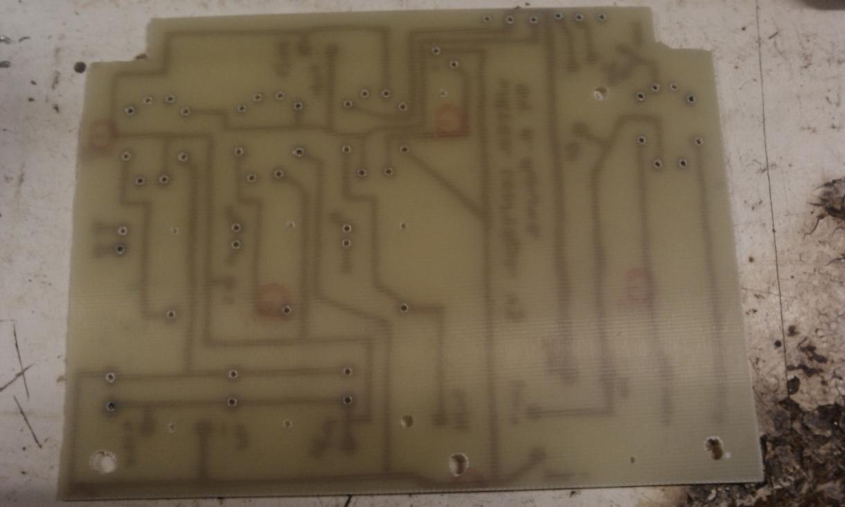
FRONT
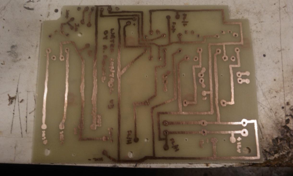
BACK
Then onto mounting components and soldering.
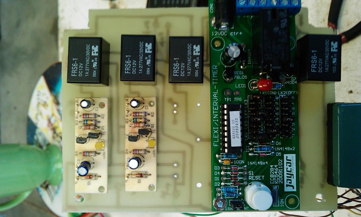
Most of the components were from Jaycar but i plan on building all my own CCTs. This is basically now modular. If the timer fails for some reason... I just de-solder a few pins and replace it.
Just some close ups
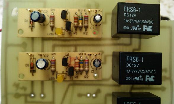
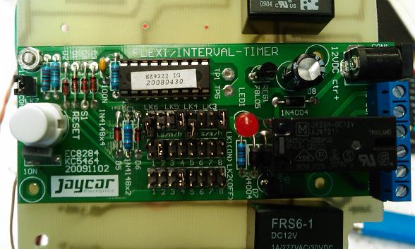
And then mounted into a box.
Again... this was my final version.. with just water control. It eventually had a lighting and motor control function, back up power with custom designed changeover CCT and a few other fancy features.
Ill go through its functions as i show the inputs and outputs of the box.
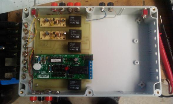
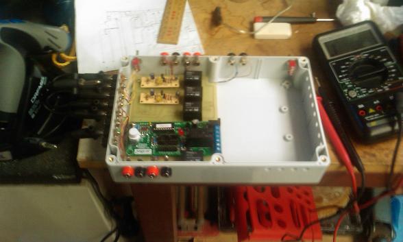
Ok now the Controls, Inputs and Outputs
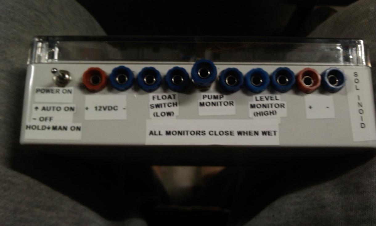
Controls from Left to Right. All inputs are banana plugs to twin core cable that run to corresponding components on the setup.
-Power on switch... pretty simple.
But a 3 way switch. Off, On and Toggle on.
So if i leave it on.... it will auto run and control the water solenoids as designed. The solenoid is connected to mains water supply at all times with the feed pipe in the water supply tank.
If I switch and hold down... it will manually operate the solenoid to fill up any water supply tanks.
Obviously...Off means off :)
-Power supply Positive and Negative.
Now the supply... i was using a 12VDC switch mode power supply. I also had a battery back up with automatic change over... Like an Uninterruptible Power Supply or UPS.
-Float switch Low
In the water storage tank i have a Jaycar float switch that is set up to monitor the water level low point. This prevents the tank going dry and will prevent any pumps burning out.
On operation i would get an alert (ill get into that)
-Pump monitor
so a Twin Core Cable is ran to any pump you want to monitor. I run the cable down the feed pipes externally and then.. tuck it in the hole..so its in constant contact with the water. So now if there is any flow issues with the pump or the pipe gets blocked etc.... a component using a very low resistance reading... enough to use water as a conductor.. will sense that there is no water.... and send an alarm plus automatically switch on the solenoid. The idea here...say for plants... the solenoid feed pipes would be placed at the base of the roots or water trough... so when the pump stops... you could be absent for weeks and the mains water will still feed the plants or container. Usually this is an enclosed system such as recirculated nutrient (drains back to main water storage) or from one tank to another (say using the water from the fish tank or pond to then water plants like your herbs or vegetables... usually using the root system to filter the water ready for entry back to the pond or fish tank...Aqua or Hydroponics or as im Terming Turtle-Ponics :))
-Level monitor
Again a float switch but this time for max level. Mainly required because...if the pump gets blocked you now have a constant feed of water till it his max level. Once the level is reached you get an alarm and the timer will go through a series of functions like only running the water at intervals... based on flow rate and evaporation levels to ensure it will continue to run without overflow.
-Solenoid Supply. 12VDC out to a 12VAC solenoid i picked up at Bunnings in the retic section. Had issues with the timer due to back emf but fixed with the use of a zenor diode on the supply.
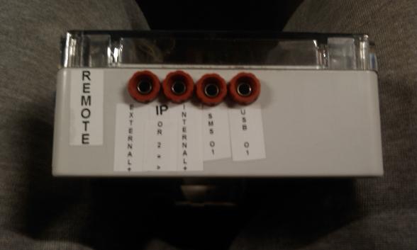
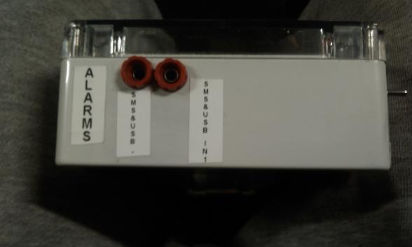
INPUTS
-Internet Control via a module i had that has its own server... I could log in at any time and use 4 different ON/OFF inputs to control 4 devices. This is in a time where we didn't have Playstore and smart phones. So now i can make this far more user friendly but considering this was probably 10 years ago now.....Think I'm ahead of the curve a little :)
-SMS
Now the controller for this was pretty cool... with 2G offline it doesn't work anymore but i can make it work with current tech and there are much better options now but it ran off of Nokia 5110. It is still working as of 2019... battery fine. It was actually a very techie phone. Had 2G so could still use to make calls and sms till 2016 i think it was... And used what was called FBUS so had a complicated text recognition and output function via its data port. so plugged into a sms converter.....
I now had 8 inputs and 8 outputs to remotely control and monitor anything that went On/Off... like a front gate or your letter box. every time it was opened...via the use of a micro switch i would get an sms saying "GATE OPEN" and "GATE CLOSED" etc. All fully customised alerts...programmed via sms.
I could also customise messages... so send "PUMP ON" and operate my pool pump or "SPA ON" which had to be the most used....
I could send "SPA ON" while i was out somewhere... my spa was gas heated with an Instantaneous Unit, the solenoid operated by the sms , heat turns on...and within an hour or 2 my spa was hot ....waiting for me to get home :)
-USB
I also had a controller for my PC. So via a program i could operate every device while sitting in my chair :) also runs an android app so phones or tablets could connect. Now Bluetooth, WiFi is used etc.
OUTPUTS
Much the same idea.... USB, Email, SMS alerts
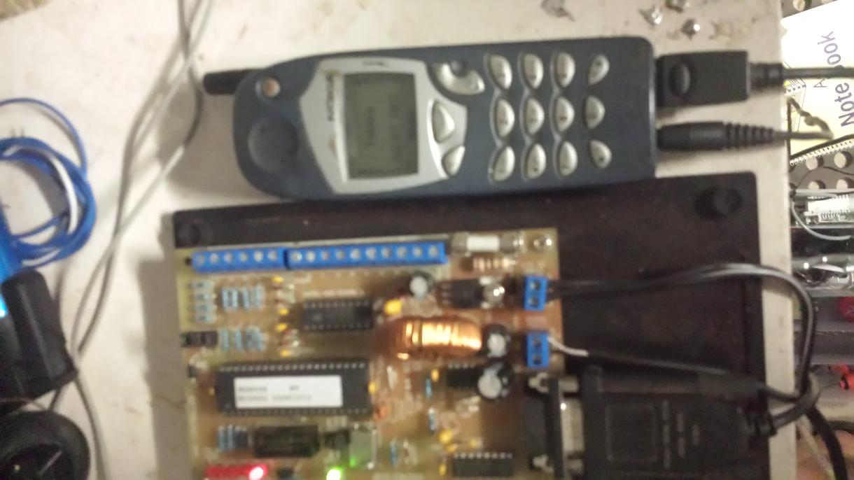
SMS CONTROLLER
Below are the PDFs explaining its operation etc

|
SMS controller part 1.pdf Size : 2293.856 Kb Type : pdf |

|
SMS controller part 2.pdf Size : 1140.813 Kb Type : pdf |
Well that's about it for this one.
Continue on below for more projects as i add them but below is the full Picture Gallery of the above project
RASPBERRY PI
I've only just began to play around with this thing.
Pretty cool what you can do with a 60 dollar micro computer and some sensors.
Ill add to this in detail as I go along but here is a Picture Gallery for now
This is basically doing the job of my original water controller....but fully digital.... and with far more going on.
It runs my Turtle tank.
So...the big green screen....is just a screen for now... Its a PiTOP CEED. The actual pi can be seen... the credit card sized thing on the bottom right.
All the connections are made with breadboard and plug wires...eventually ill make a pretty box with a touch screen interface.
Monitoring
-Water levels high /low. Has an audible alarm and email alerts or WiFi alerts if I'm home. will also auto fill the tank on water low and do a weekly water change all on its own
-Water Temp. Both digital and analog readings. All daily converted to .cvs for a trend of his tank temp
-Basking Area control (the plastic tub).
It monitors both temp and humidity. The area is climate controlled with the use of a fan and basking lamp. the lamp is activated by motion or temperature (to save power). also monitoring room temp and humidity
-Remote viewing via 3 Raspi Cams. 1 in the basking area, 1 on the side of the tank and 1 to view the entire setup. Also fitted with flame detection...always a good idea when you have tanks...water...power etc. I can see him whenever i want...whenever i want...via apps or pc
I might set up a live stream of one of his cameras here for people to see him... i love watching him eat :).
-Lighting control. Staged LED strip lighting. Blue for the first hour before "Daylight" which is based on true sunset times. Lights come on in brightness increments to simulate a sunrise and Dawn scenario...then comes on his UVA/B lighting.
Blue comes back on so one end of his tank is "dark". At sunset you get the reverse........Staged down lighting to simulate sunset / dusk and blue remains on for around 2 hours after.... so i can see him at night but he gets to sleep if he wants :)... but also sort of simulating the moon... that would be my next addition.. moonshine based on moon phases.
-Motion activated customised digital display. Can scroll text, sensor readings, dates, reminders, alarms. here is a video of the screen
Ill keep adding to this as i take more pics
But here is Cecil having a bite....... Caution....They are not as friendly as you might think....They love live food :0
And just a quick demo of the sound function controller for his tank... and my room... all synced up if i choose :)
Below you will find 2 PDFs.... these are examples of the sensors available

|
XC4288-manualMain.pdf Size : 798.949 Kb Type : pdf |

|
E014.Arduino Sensor Kit 2016-03-13.pdf Size : 1948.304 Kb Type : pdf |
The below are PDFs showing some of the Bluetooth or WiFi components i have experimented with

|
12V 2.4G Bluetooth Relay Android Mobile Remote control for Light Switch Lock.pdf Size : 2787.409 Kb Type : pdf |

|
5V-24V Bluetooth Receiver Relay Module Android Mobile Remote Control Switch LED _ eBay.pdf Size : 456.672 Kb Type : pdf |

|
New HC-SR501 Infrared PIR Motion Sensor Module for Arduino Raspberry pi _ eBay.pdf Size : 3271.511 Kb Type : pdf |

|
4 pcs x Body Load Cell Weighing Sensor Resistance strain Half-bridge Total 200kg _ eBay.pdf Size : 477.055 Kb Type : pdf |
Ill Keep adding to this list
SYNC BOX
This is just a CCT I made for work .
Unfortunately the pics are a bit dark but basically it was a 3 phase sync box.
Using a battery and buzzer in the box....with a relay and some roll out leads...... we would hook this up across any open contact and adjust all 3 phases to close at the same time.
Red light indicates contact...all 3 make contact "BEEEEEP"
MY ELECTRONICS DATABASE

|
Electronics Database.xlsx Size : 1273.834 Kb Type : xlsx |